
|
|
|
YES Multifilter Rotating Shadowband Radiometer (MFR-7) The Multifilter Rotating Shadowband Radiometer (MFR-7) measures total, diffuse, and direct irradiance with a broad-band silicon pyranometer and at six wavelengths using sensors with narrow band filters at 415, 500, 615, 673, 870, and 940 nanometers. The full width half maximum width is ten nanometers. The head, where the sensors are located, is thermally stabilized to significantly reduce uncertainties associated with temperature variation. The MFR-7 makes measurements simultaneously across all seven channels. The shadowband enables the instrument to measure the global and diffuse components of solar irradiance and then calculate the beam component. The MFR-7 system includes the YESDAS-2 datalogger. MFR-7 Radiometer Assembly 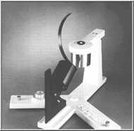 The MFR-7 Radiometer Assembly consists of the
MFR-7 sensor head along with a rotating shadowband that is driven by a stepper motor: both
are mounted
on a common base. An electronics enclosure, mounted below the Detector Assembly,
contains a YESDAS microprocessor-driven data acquisition and control system. The
system electronics has 13-bit A/D conversion accuracy and has the capability of
collecting data from an additional 24 analog and six pulse/counting-type
meteorological sensors.
The MFR-7 Radiometer Assembly consists of the
MFR-7 sensor head along with a rotating shadowband that is driven by a stepper motor: both
are mounted
on a common base. An electronics enclosure, mounted below the Detector Assembly,
contains a YESDAS microprocessor-driven data acquisition and control system. The
system electronics has 13-bit A/D conversion accuracy and has the capability of
collecting data from an additional 24 analog and six pulse/counting-type
meteorological sensors.Specifications
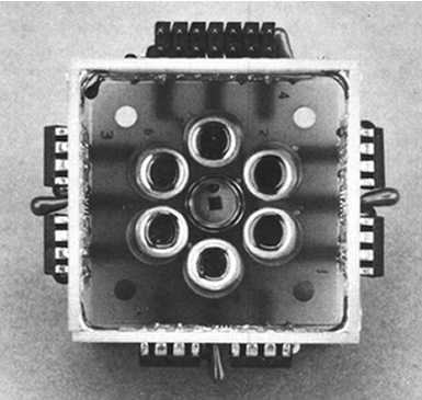
(Above: interior optical detector assembly) Control and Data Logging System The MFR-7 instrument operation and data logging are controlled by a microprocessor. This on-board CPU: 1) performs the required ephemeris calculations, 2) controls the stepper motor which positions the shadowband, 3) controls the acquisition, processing and storage of sensor data for the MFR-7 and up to 24 additional analog meteorological sensors, and 4) permits simultaneous data telemetry. The very stable system time keeping (with an accuracy of 1 second per month) ensures that the positioning of the shadowband will be precise over extended time periods, with no need for operator intervention or adjustment. 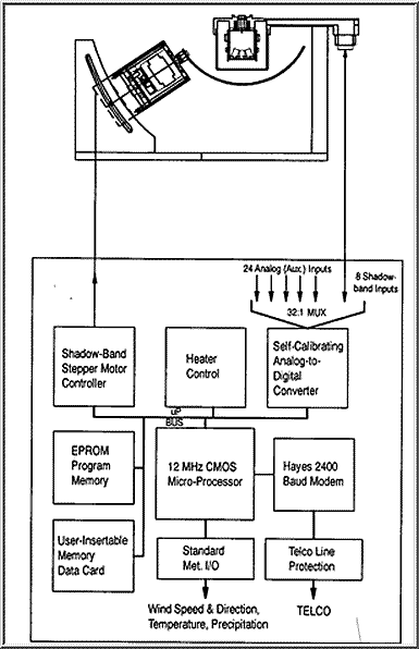
Calibration Facilities The usefulness of any instrument depends critically on the quality and long-term stability of its calibration. Yankee Environmental Systems, Inc. has fully equipped optical laboratories to completely characterize the performance and calibrate each MFR-7 instrument. The cosine, spectral, and absolute responses of each wavelength channel of the instrument are measured with NIST-traceable optical and electronic equipment and test results are supplied with each system. Interference filters deteriorate over time and yearly recalibrations of the MFR-7 are recommended. Spectral Response The spectral response of each wavelength channel of the MFR-7 instrument is measured in YES's laboratory. Below is a graph showing the typical filter passbands of an MFR instrument. 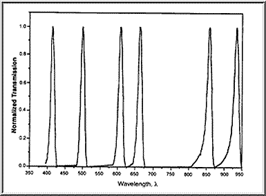
Absolute Response The absolute response of each wavelength channel of the MFR-7 instrument is measured using a 1,000 watt FEL NIST-traceable spectral irradiance standard light source. The spectral response of the channel and the output of the instrument in response to the irradiation by the FEL lamp are used to obtain the channel calibration constant. Cosine Response The MFR-7 belongs to a class of instruments that measure flux incident on a horizontal surface. The response of such instruments to radiation incident at an angle, q, with respect to the surface normal is called the cosine response. The ideal cosine response is proportional to the cosine of the angle q, and any deviation from this response introduces measurement errors. 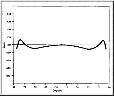
The cosine response of each MFR-7 is fully characterized in YES's angular test facility. Each instrument is tested by placing it on a computer-controlled rotary actuator and measuring the instrument response as a function of its angle with respect to a feedback-stabilized, parallel, uniform light beam. The individual MFR-7 cosine response, supplied with each instrument, is used by YESDAS system software to correct, in real time, for deviations from the ideal cosine response. © 2022, UO Solar Radiation Monitoring Laboratory.
Home page URL: solardata.uoregon.edu |